
A solar installation can look simple from the roof, yet one wrong connection can affect the entire system. Solar panels produce DC electricity, while your home appliances typically use AC power, so the system needs correctly sized wiring, protection devices, and an inverter to move electricity safely through the setup. Nigeria Electricity Supply and Installation Standards Regulations (NESIS) also cover important requirements around earthing and electrical wiring.
That raises practical concerns for anyone planning solar in Nigeria. How should panels connect to the inverter? Where should the battery, protection devices, and changeover equipment sit? What changes between an off-grid, hybrid, and grid-connected setup? Poor planning can cause power losses, equipment problems, and serious electrical safety risks.
This guide breaks down the solar installation wiring diagram for common setups in clear, simple terms. You’ll see how the major components connect and what each part does. GVE Group can also help you move from a diagram to a properly designed solar solution, with professional system planning, quality components, and installation support suited to Nigerian homes and businesses.

What a Solar Installation Wiring Diagram Shows
A solar installation wiring diagram acts like a roadmap for the entire electrical system. It shows how electricity moves from the solar panels through the charge controller or inverter, into the battery bank where applicable, and finally to the appliances or distribution board.
Main Components and Their Functions
A typical diagram may show:
| Component | Main purpose |
| Solar panels | Generate DC electricity from sunlight |
| Charge controller | Regulates power going into the batteries |
| Inverter | Converts DC electricity into AC electricity for appliances |
| Battery bank | Stores energy for later use |
| Cables and connectors | Carry electricity between components |
| Breakers, fuses and isolators | Help protect and disconnect circuits |
The exact arrangement depends on whether you choose an off-grid, hybrid or grid-connected system. The diagram should therefore match the equipment specifications rather than relying on a generic drawing.
Following the Flow of Electricity
A simple battery-backed system may follow this path:
Solar panels → protection → charge controller/inverter → battery → inverter → distribution board → appliances
Some modern hybrid inverters combine several functions, so the physical wiring can look different from this simplified flow.
Understanding Voltage, Current and Power
Voltage, measured in volts (V), describes electrical potential. Current, measured in amps (A), describes the flow of electricity, while power, measured in watts (W), combines the two.
These figures matter when designing a system. For example, knowing how much energy a solar panel makes helps you estimate how many panels you need for your daily electricity demand. GVE’s Nigeria-focused solar production guide explains that actual output changes with location, season, sunlight, and system conditions.
Solar Panel Wiring Configurations
The connection between your panels determines how the solar array handles voltage and current. The three main arrangements include series, parallel, and series-parallel wiring.
#1. Panels Connected in Series
Series wiring connects the positive terminal of one panel to the negative terminal of the next. The voltage increases while the current remains approximately the same.
This setup can work well where the inverter or charge controller requires a higher PV voltage. However, shading across a string can affect its performance, so panel placement matters.
#2. Panels Connected in Parallel
Parallel wiring connects the positive terminals together and the negative terminals together. The voltage remains similar to an individual panel while the available current increases.
This arrangement can offer more flexibility where shading affects individual panels, although higher current can require larger cables and appropriate protection.
#3. Series-Parallel Panel Connections
Larger systems can combine both methods. Installers can first create several series strings and then connect those strings in parallel.
This approach helps balance the voltage and current requirements of the inverter while allowing a larger solar array.

How Shading Affects Each Configuration
Shading deserves attention in Nigerian installations, particularly where nearby buildings, trees, water tanks, or roof structures can block sunlight.
A good design considers:
- Roof orientation and available sunlight
- Panel spacing and positioning
- Different shading conditions across the roof
- The inverter’s MPPT configuration
- Expected changes in sunlight throughout the day
A professional installer should calculate the system against the actual site rather than selecting a configuration from a diagram alone.
12V Solar Installation Wiring Diagram
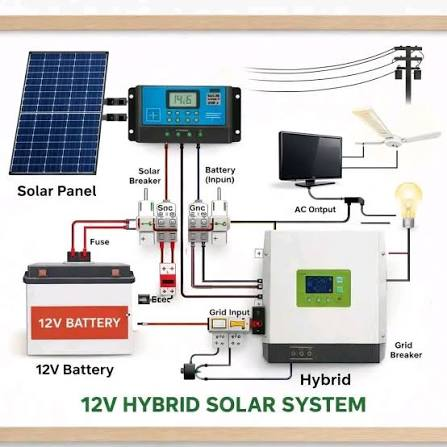
A 12V solar installation wiring diagram suits smaller, low-voltage applications and some compact backup systems. The design normally keeps the solar array, battery bank and compatible equipment within the required voltage range.
Single-Panel 12V System
A basic setup connects one suitable solar panel to a charge controller, then to the battery. The controller manages the charging process instead of allowing the panel to connect directly to the battery.
The battery then supplies a suitable inverter or DC loads, depending on the system design.
Multiple Panels in Parallel
Multiple compatible panels can connect in parallel when the system needs more current without increasing the nominal array voltage.
For example, two panels with matching electrical characteristics can feed a common connection point before the charge controller. The installer must still check the controller’s maximum PV current and voltage ratings.
12V Battery and Inverter Connections
The battery-to-inverter connection requires particular attention to cable sizing, polarity and protection. Higher loads can draw substantial current from a 12V battery bank, which can make cable selection increasingly important.
A 12V setup therefore makes more sense for smaller loads than for a large Nigerian home with several air conditioners, pumps and other heavy appliances. Larger installations generally benefit from higher system voltages.
24V Solar Installation Wiring Diagram
A 24V solar installation wiring diagram provides a practical middle ground for systems that need more power than a typical 12V arrangement can comfortably handle.
Two Panels in Series
Two compatible 12V panels can connect in series to raise the array voltage. The resulting voltage must remain within the acceptable operating range of the selected charge controller or inverter.
The same principle can apply to batteries: compatible 12V batteries can form a 24V battery bank when connected correctly.
24V Series-Parallel System
A larger 24V system can combine series and parallel connections. For example, installers can create pairs of panels in series and then connect matching pairs in parallel.
This arrangement can provide the required voltage while increasing the available current for the overall array.
24V Battery and Inverter Connections
The inverter should match the battery bank’s nominal voltage and provide enough capacity for the intended loads.
Before installation, check:
- Inverter input voltage
- Maximum PV voltage
- Maximum PV current
- Battery voltage
- Battery capacity
- Cable ratings
- Required protective devices
These checks matter more than simply copying a 24V diagram from another installation.

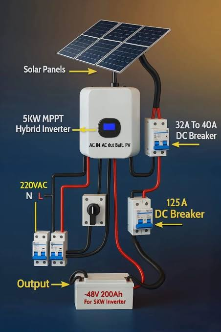
48V Solar Installation Wiring Diagram
A 48V solar installation wiring diagram commonly suits larger residential, commercial and off-grid systems where higher power demands make lower-voltage battery systems less practical.
Solar Panel String Arrangement
The panels can form series strings to reach the voltage range required by the inverter. Several strings can then operate in parallel where the system design calls for additional current.
The installer must calculate the string voltage against the inverter’s limits rather than assuming that any number of panels will work together.
48V Battery Bank Connections
A 48V battery bank can store energy for use when solar production falls or during grid outages. The battery specifications must match the inverter and battery-management system where applicable.
The system should also allow appropriate isolation and protection for maintenance and fault conditions.
Inverter and Protection Connections
The inverter forms the main link between the DC side and the AC loads. A properly designed 48V setup can include DC protection, battery isolation, AC protection, earthing, and other safety equipment appropriate to the installation.
For larger projects, Nigerian regulatory requirements also matter. The Nigerian Electricity Regulatory Commission (NERC) publishes electricity-industry codes and regulations, including current health and safety resources and the Mini-Grid Regulations 2026. Projects that fall within the mini-grid framework require the applicable registration, permit, or authorisation.
For homeowners and businesses that want a professionally designed system rather than a generic diagram, GVE Group provides residential, commercial, industrial and rural renewable-energy solutions in Nigeria, including solar design, installation and maintenance.
Solar Installation Wiring Diagram for Nigerian Homes
A Nigerian home needs a solar design that reflects how the household actually uses electricity. A system for a two-bedroom apartment with lights, fans, TV, and a refrigerator will have different requirements from one serving a larger home with air conditioners, water pumps, and other high-load appliances.
Off-Grid Solar Setup
An off-grid system works independently of the public electricity network. Solar panels charge the battery bank, while the inverter supplies AC power to the selected household circuits.
This setup can suit homes in areas with limited grid access or households that want their essential loads to operate independently.
Grid-Tied Solar Setup
A grid-tied system works alongside the public electricity supply. Solar generation can supply household loads while the grid provides additional power when solar production cannot meet demand.
A grid connection requires more than simply adding solar panels to an existing distribution board. The equipment, protection, and connection arrangement must follow the applicable requirements for the installation.
Hybrid Solar Setup
A hybrid system combines solar generation, batteries, and grid or generator input. This arrangement can suit Nigerian homes that want solar power during the day, battery backup during outages, and another power source when the battery reaches its limit.
The inverter manages the available energy sources according to the system design and programmed settings.
Connecting Solar to the Home Distribution Board
The final connection to household circuits requires careful planning. The installer should identify which appliances need backup power and separate heavy or unsuitable loads where necessary.
A typical arrangement may include:
Solar array → inverter/protection → distribution board → selected household circuits
NERC maintains current industry codes, including the Health & Safety Code for the Nigerian Electricity Supply Industry, Second Edition (March 2026). Installations should also follow the relevant equipment manufacturer’s instructions and applicable electrical requirements.
For homeowners who want a professionally designed system, GVE Group provides customised residential solar installations and energy solutions in Nigeria. Its residential offering covers system design, installation, and support based on individual energy requirements.
Essential Components for Solar Wiring
A reliable solar installation wiring diagram should account for more than panels and an inverter. Protection, isolation, and suitable connections all form part of the electrical design.
#1. Solar Cables and MC4 Connectors
Solar cables carry DC power between the panels and other equipment. MC4-type connectors commonly provide the panel-to-cable connection.
The cable and connector ratings should match the expected voltage, current, and environmental conditions. Outdoor wiring also needs suitable protection from sunlight, heat, moisture and physical damage.
#2. Fuses, Breakers and DC Isolators
Protection devices help limit the consequences of faults and allow sections of the system to disconnect safely for maintenance.
The exact protection arrangement depends on the system design, equipment ratings, and applicable requirements. A diagram should show these devices rather than treating them as optional accessories.
#3. Charge Controllers and Inverters
The charge controller manages energy going from the solar array into a battery bank in systems that use a separate controller.
The inverter handles the conversion from DC to AC and, in hybrid systems, can coordinate different power sources and battery operation. Modern hybrid inverters can combine functions that previously required several separate devices.
#4. Earthing and Surge Protection
Earthing provides an important safety path for electrical faults, while surge protection helps protect equipment from transient overvoltage.
The correct arrangement depends on the building, equipment and installation design. A qualified installer should determine the appropriate protection rather than copying a protection layout from another property.
Choosing Between MPPT and PWM
The charge controller can influence how effectively a battery-based system uses available solar power. MPPT and PWM controllers perform the same broad charging-control role, but they use different approaches.
How PWM Works
A PWM controller regulates the connection between the solar array and battery. It works best when the panel voltage closely matches the battery system voltage.
Its simpler design can suit smaller and less demanding installations.
How MPPT Works
An MPPT controller continually adjusts its operating point to extract useful power from the solar array while matching the battery’s charging requirements.
This approach can prove particularly useful where the solar array operates at a higher voltage than the battery bank.
Which Controller Fits Your System?
| Consideration | PWM | MPPT |
| System complexity | Simpler | More advanced |
| Panel/battery voltage matching | More important | More flexible |
| Larger solar systems | Less suitable in many designs | Often more suitable |
| Cost | Generally lower | Generally higher |
| Design flexibility | More limited | Greater |
The choice should follow the panel specifications, battery voltage, array size, and inverter/controller requirements, rather than price alone.

Solar Wiring Mistakes to Avoid
Small wiring decisions can create larger problems later. These mistakes deserve attention before installation begins.
Exceeding Inverter Voltage Limits
Never select a panel string without checking the inverter’s permitted PV voltage and current range. The calculation should account for the actual operating conditions, not just the nominal figures printed on the panel.
Using Incorrect Cable Sizes
Undersized cables can increase voltage drop and heating. Oversizing every cable, however, can unnecessarily increase installation costs.
Choose the conductor according to the calculated current, distance, voltage drop and installation requirements.
Mixing Incompatible Components
Panels, batteries, charge controllers and inverters must work within compatible electrical ranges.
Check the manufacturer’s specifications before combining equipment, particularly when expanding an existing installation.
Connecting Batteries Without Proper Protection
Battery circuits need appropriate isolation, protection and correctly sized cables. A diagram should clearly show how the battery connects to the rest of the system.
Ignoring Isolation and Earthing
Maintenance becomes more difficult when installers omit proper isolation points. Earthing and other protective measures also need consideration from the design stage.
Frequently Asked Questions
Can I use the same wiring diagram for every Nigerian home?
No. System size, appliance demand, battery capacity, inverter specifications, panel arrangement, and site conditions can change the required design.
Should I copy a solar wiring diagram from another installation?
Use diagrams as learning and planning references, not as a substitute for system design. The final wiring should match the exact equipment and site.
What determines the correct cable size?
The main factors include current, voltage, cable length, voltage-drop limits, installation conditions and equipment specifications.
Can I add more solar panels to an existing system later?
Potentially, but the existing inverter, charge controller, cables, protection devices and panel string limits must support the expansion. A professional should assess the existing system before additional panels or batteries join it.
Does GVE Group install solar systems for homes in Nigeria?
Yes. GVE provides residential solar solutions and custom installations designed around individual household energy requirements. The company also works across commercial, industrial and rural electrification projects.